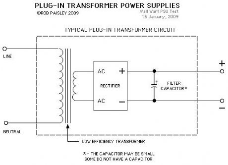

In this case, the power from the transformer in the air conditioning system would go to the thermostat terminal. A transformer for cooling and a transformer for heating. RC – The RC terminal is designated for the power for cooling. *Although be aware that this may have changed especially if the person who wired the thermostat didn’t use conventional color coding. If you have a package unit then the transformer is in the package unit.

For this reason, it is a good idea to kill the power at the condenser and the air handler before changing or working on the wiring at the tstat. This is a red wire and comes from the transformer usually located in the air handler for split systems but you may find the transformer in the condensing unit. Thermostat Wire Colors Code | HVAC Control Thermostat Wiring and Wire Color Chart – Thermostat Wiring Colors Code

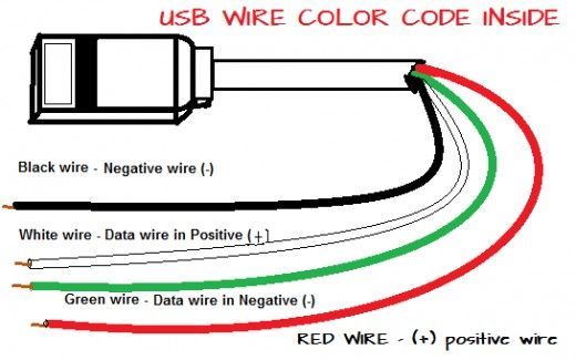
For the rest of the article see - and lastly see this - which concerns international colour codes in electronics.Always make sure you have the right tools and materials for the job. Two wires of each color were provided for each circuit, and phasing was not identified by the color code." end quote. Black was the primary connection, red secondary for the B+ (plate voltage), red with a yellow tracer was the center tap for the B+ full-wave rectifier winding, green or brown was the heater voltage for all tubes, yellow was the filament voltage for the rectifier tube (often a different voltage than other tube heaters). "Power transformers used in North American vacuum-tube equipment were often color-coded to identify the leads. I have several tfmrs with red leads for 230/240v and light blue for 110/120v.įrom a quick search, found this - & this - wiki has this to say - quote. Tfmr's in some Telequipment scopes follow a similar theme, but when you think about it, if you have a bit of kit made for USA/EU/ASIA mains voltages with several primaries, wire colours are bound to be of the primary colours, stripped/two colour coded wire being less common.


 0 kommentar(er)
